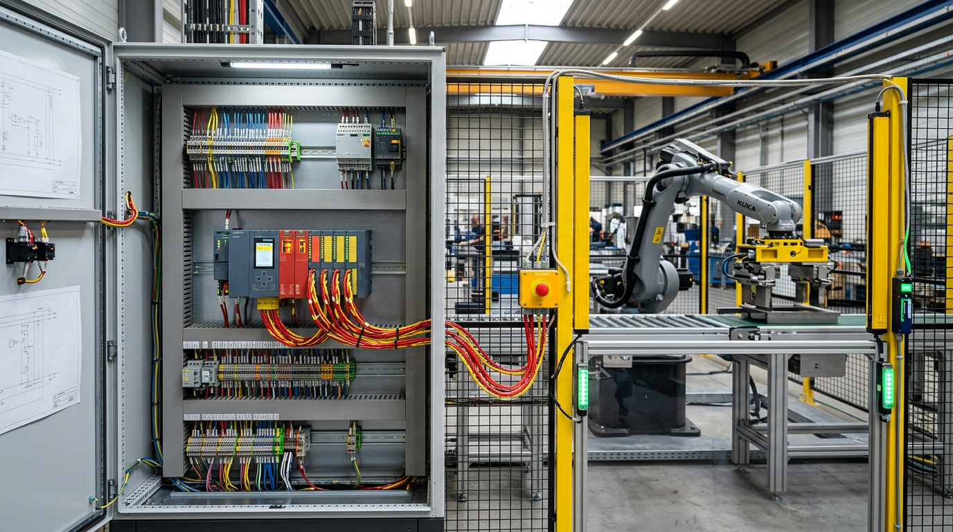
In our journey across the Digital Chain, we have wired 24VDC power, measured micro-fluctuations in 4-20mA analog loops, tuned PID controllers to sub-percent stability, commanded VFDs over Device Level Ring (DLR), and bridged edge telemetry into MQTT brokers.
Yet sooner or later, every engineering student, junior integrator, or software programmer entering an industrial facility asks the exact same question:
“I have an emergency stop mushroom button on my machine. Why can’t I just wire it into a standard 24VDC digital input card, write an
XICcontact in my standard ladder logic, and unlatch the motor contactor coil?”
The short answer: If you do that, you have created a severe safety liability, violated international machine safety directives, and built a system that will inevitably fail dangerously.
In this deep dive, we unpack the mechanical and mathematical realities of functional machine safety under ISO 13849-1 and IEC 62061, uncover the internal architecture of Safety PLCs, examine how pulsed test signals catch physical wiring shorts, and discover how modern safety fieldbuses control hardware Safe Torque Off (STO) terminals without cutting high-voltage mains.
1. The Fatal Assumption: Standard Software vs. Deterministic Failure
To understand why standard PLCs are forbidden from executing safety functions, you must understand how hardware fails.
Standard consumer and industrial electronics are designed for availability and functional performance: they are built to keep running as long as possible. A Safety Instrumented System (SIS) is engineered around a completely different mandate: predictable, fail-safe degradation in the presence of random and systematic faults.
[ STANDARD PLC LADDER LOGIC: THE ILLUSION OF SAFETY ] E_STOP_PB SAFETY_OK MTR_RUN_CMD CONTACTOR_COIL-----| |-------------| |--------------| |--------------( )------ Input 0.0 Internal Bit Output 0.0THREE WAYS THIS FAILS TO OPEN WHEN AN OPERATOR PRESSES E-STOP:1. Microprocessor Memory Glitch: A cosmic ray or EMI spike flips the bit for Input 0.0 to '1'.2. Transistor Output Failure: The output transistor on Output 0.0 welds internally into a permanent short to +24VDC.3. Cable Pinch: The wire between the E-stop and the panel pinches against the steel frame, shorting the conductor to +24VDC before reaching the switch contact.===> RESULT: OPERATOR CRUSHED DESPITE DEPRESSING THE EMERGENCY STOP.
The Three Vulnerabilities of Standard PLCs
- Dangerous Undetected Hardware Failures: A standard transistor output card uses single silicon MOSFETs or triacs. When solid-state switches fail under thermal stress or inductive back-EMF, they almost always fail closed (shorted). If an output transistor shorts internally, the PLC CPU can command the output to turn OFF, but current continues flowing to the motor contactor coil.
- Firmware and Operating System Freezes: A standard PLC operating system does not have hardware-isolated lockstep dual-core processors. If a firmware loop hangs, a watchdog timer might eventually trigger, but during those critical 200–500 milliseconds, an operator cannot stop the machine.
- No Dynamic Wiring Diagnostics: A standard DC input card simply checks whether voltage is present (> 15 VDC = High, < 5 VDC} = Low). If a field wire pinches against a 24V conduit or short-circuits to an adjacent wire, the standard card sees 24VDC and assumes the E-stop switch is closed and healthy. It has zero capability to detect wiring faults.
2. Demystifying ISO 13849-1: The Performance Level (PL) Risk Graph
Machine safety in global automation is governed by ISO 13849-1 (Safety of machinery — Safety-related parts of control systems). Instead of arbitrary guessing, ISO 13849-1 uses a structured risk graph to determine the Required Performance Level (PL_r), ranging from PL_a (lowest risk) to PL_e (highest risk).
                 [ SEVERITY OF INJURY ]
                      S1: Slight (reversible injury, cuts, bruises)
                      S2: Serious (irreversible injury, amputation, fatality)
                           |
                           v
                 [ FREQUENCY / EXPOSURE TIME ]
                      F1: Seldom to less often, and/or short exposure
                      F2: Frequent to continuous, and/or long exposure
                           |
                           v
                 [ POSSIBILITY OF AVOIDANCE ]
                      P1: Possible under specific conditions (slow motion, escape space)
                      P2: Scarcely possible (high speed, enclosed cell, crushing hazard)
                     +--- P1 ------------> PL b
              +-- F1 |
              |      +--- P2 ------------> PL c
       +-- S1 |
       |      |      +--- P1 ------------> PL c
       |      +-- F2 |
START -+             +--- P2 ------------> PL d
       |
       |             +--- P1 ------------> PL c
       |      +-- F1 |
       |      |      +--- P2 ------------> PL d
       +-- S2 |
              |      +--- P1 ------------> PL d
              +-- F2 |
                     +--- P2 ------------> PL e  <=== ROBOT CELLS, PRESSES
What Does Performance Level Actually Mean?
A Performance Level is a quantified probability of dangerous failure per hour ($PFH_d$):
| Performance Level (PL) | Probability of Dangerous Failure per Hour (PFHd) | Equivalent SIL (IEC 62061) | Typical Machine Application |
| PLa | 10-5 <= PFHd < 10-4 | No equivalence | Minor pinch point; low force conveyor feed |
| PLb | 3 x 10⁻⁶ <= PFHd < 10-5 | SIL 1 (PFHd > 10-6) | Small packaging station with interlocked inspection flap |
| PLc | 10-6 <= PFHd < 3 x 10⁻⁶ | SIL 1 | Pallet wrapper gate; automated door interlock |
| PLd | 10-7 <= PFHd < 10-6 | SIL 2 | Overhead transfer gantry; high-speed labeling machine |
| PLe | 10-8 <= PFHd < 10-7 | SIL 3 | Robotic welding cell; metal forming stamping press; automated saw |
To achieve PL_e, your safety system must experience less than one dangerous failure in 10,000,000 operating hours (over 1,140 years of continuous operation). Achieving that level of statistical certainty is physically impossible using standard software and single-channel wiring.
3. The Four Pillars of Performance Level
Achieving a target $PL$ requires satisfying four interrelated engineering metrics:
- System Architecture (Category B, 1, 2, 3, or 4): The structural topology of the hardware (single-channel vs. dual-channel redundant with diagnostics).
- Mean Time to Dangerous Failure (MTTF_d): Statistical reliability of individual physical components:
- Low: 3 years <= MTTF_d < 10 years
- Medium: 10 years <=MTTF_d < 30 years
- High: 30 years <=MTTF_d <= 100 years
- Low: 3 years <= MTTF_d < 10 years
- Diagnostic Coverage (DC_avg): Percentage of dangerous failures that the control system automatically detects through self-testing:
Diagnostic Coverage = \frac{\sum \lambda_{dd}}{\sum \lambda_{d,\text{total}}} \times 100\%$$- None: DC < 60%
- Low: 60% <= DC < 90%
- Medium: 90% <= DC < 99%
- High: DC >= 99%
- None: DC < 60%
- Common Cause Failure (CCF): Defenses against common external events disabling both redundant channels simultaneously (lightning, ground bounce, physical cable routing through the same pinch point, or temperature extremes). A minimum score of >= 65 points on the ISO 13849-1 checklist is required.
4. Architectural Categories: From Single-Channel to Category 4
[ CATEGORY 1: SINGLE CHANNEL (WELL-TRIED COMPONENTS) ] Sensor (Single NC) -------> Input -------> Logic -------> Output -------> Actuator * A single mechanical or electrical fault causes immediate loss of safety function.[ CATEGORY 3: DUAL-CHANNEL REDUNDANT WITH LOCAL MONITORING ] Channel 1: Sensor Contact A ---> In 1 ---> CPU A ---> Out 1 ---> Contactor K1 | | | [ Cross-Diagnostics ] | | | | Channel 2: Sensor Contact B ---> In 2 ---> CPU B ---> Out 2 ---> Contactor K2 * Single fault will not cause loss of safety. Accumulation of undetected faults CAN cause failure.[ CATEGORY 4: DUAL-CHANNEL WITH CONTINUOUS DYNAMIC DIAGNOSTICS ] * High Diagnostic Coverage (DC >= 99%). * Faults are detected before or at the next demand. * An accumulation of multiple simultaneous faults cannot defeat safety shutdown.
5. The Magic of Safety I/O: Pulsed Test Outputs & Cross-Monitoring
How does a Safety PLC detect that an electrician accidentally pinched a wire, or that two adjacent 24VDC conductors melted together inside a flexible drag chain?
The secret lies in Pulsed Test Outputs (Dynamic Dark Tests).
Safety Output Terminal T0: ---\___/-----------------\___/----------------- (Pulse 0: 500 us low)Safety Output Terminal T1: -------------\___/-----------------\___/------- (Pulse 1: 500 us low)Normal Reading at In 0: ---\___/-----------------\___/----------------- (Matches T0 pattern)Normal Reading at In 1: -------------\___/-----------------\___/------- (Matches T1 pattern)FAULT SCENARIO A: CABLE SHORTED TO +24VDC CONSTANT RAILActual Reading at In 0: ----------------------------------------------- (Constant HIGH)Diagnostic Result: PLC expects 500 us dip from T0; sees static 24V.===> INSTANT SHORT-CIRCUIT FAULT TRIPPED WITHIN < 1 MILLISECOND!FAULT SCENARIO B: CROSS-CIRCUIT SHORT (CHANNEL 0 SHORTED TO CHANNEL 1)Actual Reading at In 0: ---\___/-----\___/------- (Sees dips from BOTH T0 and T1!)Diagnostic Result: Cross-talk detected between channels.===> SYSTEM LOCKS OUT BEFORE OPERATOR CAN EVEN INITIATE A CYCLE.
The Microsecond “Dark Test”
The safety module does not send raw, continuous +24 VDC through the E-stop contacts. Instead:
- Terminal
T0sources 24VDC, but drops the signal to 0 V for approximately 200 to 500 microseconds every few milliseconds. - Terminal
T1executes an identical dip, but offset in time (out of phase). - Because the motor contactor coil and mechanical relays have mechanical inertia (requiring >= 15 ms of continuous voltage drop to release), a 500 microsecond pulse does not cause contactors to drop out or motors to shudder.
- However, the internal high-speed microprocessors sample the incoming channel voltages every few microseconds. If Channel 0 does not replicate the exact pulse pattern generated by
T0, or if Channel 0 displays the pulse pattern ofT1, a cross-fault short circuit is diagnosed instantly.
Discrepancy Monitoring
Safety inputs evaluate contacts in pairs (e.g., dual NC contacts on an E-stop button). When you press the E-stop:
- If Contact A opens at t = 0 ms, Contact B must open within a configurable Discrepancy Time (typically set to 50 to 100 ms).
- If Contact A opens but Contact B remains closed (due to a mechanical spring failure, welded switch contact, or debris), the Safety PLC enters a Discrepancy Fault.
- The safety logic trips the cell immediately, and crucially, refuses to reset even if Contact A closes again until the machine undergoes a full diagnostic power-cycle and manual inspection.
6. From Software to Actuation: Safe Torque Off (STO) & Safety Fieldbuses
Historically, when safety tripped, engineers dropped a massive main power contactor located before the VFD.
While effective, dumping main 480 VAC power on an actively spinning drive causes severe issues:
- Destructive electrical arcing across contactor tips.
- Complete loss of regenerative dynamic braking (the load coasts uncontrolled into equipment).
- Premature failure of the VFD’s pre-charge circuit due to repetitive inrush cycling.
[ MODERN SAFETY ARCHITECTURE: CIP SAFETY / PROFISAFE TO DRIVE STO ]Safety Controller (1756-L83ES GuardLogix / S7-1500F) | | Industrial Ethernet (Black Channel: CIP Safety / PROFIsafe) | Safe packets carry timestamps, sequence counters, CRC signatures vPowerFlex 755 / SINAMICS S120 Drive +-------------------------------------------------------------+ | [ Standard Control Logic ] | | | | | v | | [ STO Hardwired Core / Safety Module ] | | +-- STO Channel A ---> Physically cuts Optocoupler 1 | | +-- STO Channel B ---> Physically cuts Optocoupler 2 | | | | | v | | [ 3-Phase IGBT Inverter ] | | Gates cannot physically fire; motor torque = ZERO! | +-------------------------------------------------------------+
What Safe Torque Off (STO) Does and Does Not Do
- What STO Does: It guarantees via redundant, hardwired hardware gates inside the drive that the IGBT inverter transistors cannot generate the rotating magnetic field required to produce motor torque. It achieves PL_e / SIL 3 without removing the incoming 480 VAC line voltage.
- What STO Does NOT Do: It does not stop a coasting load immediately unless the load has natural friction or an integrated mechanical holding brake. If a heavy vertical hoist drops when torque is removed, STO alone is insufficient: you must implement Safe Stop 1 (SS1) (controlled deceleration ramp followed by STO) or Safe Brake Control (SBC).
The “Black Channel” Principle
Modern automation eliminates hundreds of individual safety cables using Safety Fieldbuses (CIP Safety over EtherNet/IP or PROFIsafe over PROFINET).
- Safety protocols treat the underlying network (cables, managed switches, Wi-Fi bridges) as an untrusted “Black Channel.”
- The safety layer embeds sequence numbers, precise microsecond time-stamps, and 32-bit CRC mathematical signatures directly into the data payload.
- If a switch drops a packet, delays a transmission, or corrupts a bit, the receiving safety device detects the sequence or time skew and drops into safe state (< 10 ms).
7. Student Commissioning & Field Safety Checklist
When auditing a machine cell during commissioning or designing your university capstone project, run these five non-negotiable checks:
- Verify Dual-Channel Physical Wiring: Ensure emergency stop pushbuttons and safety gate interlocks use two independent, mechanically linked Normally Closed (NC) contacts wired to separate safety input channels with pulsed test outputs enabled.
- Never Cross Safety and Standard Memory Without Mapping: A safety PLC maintains an isolated safety memory partition. Standard ladder logic can read safety tags, but standard logic can never write directly to safety output tags.
- Execute the Discrepancy Fault Test: Physically disconnect one wire from Contact A of an E-stop button while leaving Contact B connected. Press the button and release it. Does the PLC detect the discrepancy fault? Does it block resetting until the contact pair is repaired? If it resets normally, the configuration is invalid.
- Audit the Reset Rung (Manual Monitored Reset): Re-engaging an E-stop button must never automatically restart physical machinery. Safety standards mandate a separate, intentional Manual Monitored Reset action occurring only after the safety envelope is proven clear.
- Calculate Your Risk Graph (PL_r): Document the Severity (S), Frequency (F), and Avoidance (P) for every hazardous motion. Verify that your hardware components (contactors, interlocks, drives) carry a certified rating equal to or higher than the required PL_r.
Interactive Lab: Open the ISO 13849-1 Risk Graph & Dual-Channel Safety Lab below. Calculate required Performance Levels for real-world equipment, inject simulated cable shorts and contact bounce faults, and watch how the pulsed test signals and discrepancy timers catch dangerous failures in real time.
The Functional Safety Workbench
The Functional Safety Workbench
Why standard PLCs cannot execute safety: Explore the ISO 13849-1 Risk Graph, simulate dual-channel pulsed test inputs, and diagnose short-circuit cross faults.
ISO 13849-1 Performance Level ($PL_r$) Calculator
Select application risk parameters to determine the mandatory architectural category and required diagnostic coverage.
Performance Level e
$PFH_d < 10^{-7}$ (SIL 3 Equivalent)Category 4
Dual-channel redundant + cross-testHigh ($DC \ge 99\%$)
Pulsed dynamic dark-test mandatoryHigh (30 to 100 Years)
B10d certified safety componentsDual-Channel Pulsed Test Diagnostic Simulator
Observe how a Safety PLC injects microsecond test pulses ($T0$ and $T1$) out-of-phase to instantly catch 24V short-circuits and welded contacts.
Dual NC Contacts
Comparing Safety Categories B through 4
Understanding the hardware layout behind deterministic safety.
| Category | Redundancy | Diagnostic Coverage ($DC$) | Behavior Upon Fault | Attainable PL |
|---|---|---|---|---|
| Category B | Single Channel | None (0%) | Fault causes immediate loss of safety function. Relies strictly on component robustness. | Up to PL b |
| Category 1 | Single Channel | None (0%) | Single fault causes safety loss, but probability of failure is low via “well-tried components.” | Up to PL c |
| Category 2 | Single Channel + Test Equipment | Low to Medium (60–90%) | Safety checked periodically (e.g., at machine startup). Fault between tests causes hazard. | Up to PL d |
| Category 3 | Dual Channel Redundant | Low to Medium (60–90%) | Single fault does not lose safety function. However, accumulation of undetected faults can fail. | Up to PL d / PL e |
| Category 4 | Dual Channel + Continuous Cross-Test | High ($\ge 99\%$) | Faults detected immediately at or before next demand. Accumulation of faults never loses safety! | PL e (SIL 3) |
