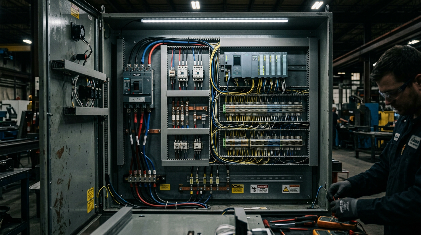
In our journey across the Digital Chain, we have wired 24VDC power supplies, mapped 4-20mA analog loops, tuned PID algorithms, configured VFD parameters, and routed deterministic CIP packets across Device Level Ring topologies. On an engineering laptop or in a software simulation, everything behaves cleanly: code compiles without errors, math converges smoothly, and virtual motors spin at the exact frequency commanded.
Then comes the day of physical startup: Commissioning Day.
You arrive on a noisy concrete production floor. The machinery smells of fresh cutting oil, anti-corrosion grease, and paint. Spools of unstripped cable lie in cable trays. Contractors are torquing conduit nuts, and plant managers are pacing the mezzanine counting the dollars lost for every hour the production line sits idle.
Inside the electrical enclosure sits $250,000 of sensitive solid-state electronics—PLCs, safety controllers, multi-axis servo drives, and network switches—connected to hundreds of feet of field wiring routed through flex conduits, drag chains, and junction boxes.
“If you flip the main 480VAC disconnect breaker right now and hope for the best, you are not commissioning a machine—you are gambling with equipment destruction, fire, and human life.”
In this comprehensive field guide, we break down the rigorous, battle-tested Five-Stage Industrial Checkout Sequence practiced by veteran controls integrators. We explore how to ring out cold circuits, safely energize control power, force I/O through standardized two-person radio protocols, bump-test uncoupled motors without shearing keyways, and maintain real-time Redline Drawings that bridge the gap between engineering drawings and factory floor reality.
Stage 0: The Perimeter of Protection (LOTO & NFPA 70E)
Before touching a terminal screwdriver or pulling your multimeter out of your Pelican case, you must establish an impenetrable envelope of electrical and mechanical safety.
+--------------------------------------------------------------------------+| STAGE 0: ZERO ENERGY VERIFICATION || || [ 480VAC Feeder ] ---> [ Padlock + Red Tag ] ---> [ Mechanical Latch ] || | || v || [ Test Before Touch: NFPA 70E Protocol ] || 1. Verify DMM on known live source (120V receptacle) || 2. Test Phase-to-Phase (L1-L2, L2-L3, L1-L3): Must be 0.0V || 3. Test Phase-to-Ground (L1-G, L2-G, L3-G): Must be 0.0V || 4. Re-verify DMM on known live source (Proves meter works) |+--------------------------------------------------------------------------+
1. Lockout / Tagout (LOTO) Discipline
Commissioning is the most dangerous operational phase of an industrial facility because mechanical interlocks are not yet active and software safety functions have not yet been certified.
- Every engineer, technician, and electrician working on the equipment must apply their own individual personal padlock and danger tag to the main energy isolating device.
- Never rely on another contractor’s lock. Never allow a “group lock” to proceed without a verified lockbox protocol.
2. The Three-Point Voltmeter Check
Never trust a digital readout when verifying zero energy. Multimeter fuses can blow, selector switches can fail internally, and probes can crack.
- Point A: Measure a known energized test source (e.g., a verified 120VAC convenience outlet) to prove your Digital Multimeter (DMM) actively displays voltage.
- Point B: Measure all phase-to-phase (L1-L2, L2-L3, L3-L1) and phase-to-ground (L1-GND, L2-GND, L3-GND) terminals downstream of the main disconnect. All readings must be strictly 0.0 VAC.
- Point C: Immediately measure the known live source again to confirm your meter did not fail during the test.
Stage 1: Cold Wire Checks (“Ringing Out” the Panel)
The main 480VAC disconnect is locked open. No power exists anywhere in the panel. Now begins the unglamorous, indispensable ritual known as Cold Wire Ring-Out.
[ COLD CHECK TARGETS: 3 FAILURE MODES TO CATCH BEFORE APPLYING POWER ]1. THE DEAD SHORT TO CHASSIS: DMM (Ohms / Beeper) between +24VDC Bus and Ground Bar. * NOMINAL: Open Loop (OL) or Megohm range. * FATAL ERROR: < 1.0 Ohm (Conductor pinched against DIN rail or conduit burr). * CONSEQUENCE OF POWERING: Instant SMPS overcurrent shutdown or melted trace.2. THE FLOATING GROUND: DMM (Ohms) between Panel Ground Bar, Subpanel, Door, and Machine Bed. * NOMINAL: < 0.2 Ohms (Bonding braid torqued star washers intact). * FATAL ERROR: > 5.0 Ohms (Painted frame insulating grounding stud). * CONSEQUENCE OF POWERING: Lethal touch potential and erratic analog sensor jitter.3. MOTOR WINDING BREAKDOWN: 500VDC / 1000VDC Insulation Resistance Tester (Megohmmeter). * NOMINAL: > 100 Megohms to motor stator frame. * FATAL ERROR: < 1.0 Megohm (Water ingress, insulation pinched in peckerhead). * CONSEQUENCE OF POWERING: Explosive phase-to-ground arc flash across VFD IGBTs.
The Ferrule and Torque Audit
During shipment, transit vibrations over hundreds of highway miles loosen screw-clamp terminals.
- Use an insulated torque screwdriver matched to terminal block manufacturer specifications (typically 0.5 to 1.2 Nm).
- Perform a gentle tug test on every field conductor entering the terminal strip. A loose ferrule inside a spring-clamp or screw-cage terminal creates intermittent, temperature-dependent communication failures that can take days to isolate later.
Insulation Resistance Testing (The Megger Test)
Before landing motor leads onto the output terminals (U, V, W) of a Variable Frequency Drive, you must disconnect the leads and apply an Insulation Resistance Tester (Megger):
- Apply 500 VDC (for 230V motors) or 1000 VDC (for 480V motors) between phase conductors and the motor frame.
- A healthy winding should read >= 100 MOhms. If a motor reads < 5 MOhms, moisture has penetrated the windings or a field wire was sliced by conduit threads. Connecting a shorted motor to a VFD will instantaneously destroy the drive’s output transistors, regardless of electronic overload settings.
Stage 2: Control Power Energization (The “Smoke Test”)
Never energize high-voltage 480VAC 3-phase power and 24VDC control power at the same time. You must isolate and verify the control brain before enabling the physical actuators.
+--------------------------------------------------------------------------+| STAGE 2: CONTROL ENERGIZATION PROTOCOL || || 1. PULL ALL BRANCH CIRCUIT FUSES (Analog, Digital I/O, Field Nodes) || 2. ISOLATE PLC POWER SUPPLY TERMINALS || 3. ENERGIZE CONTROL TRANSFORMER / 24VDC SMPS ONLY || 4. VERIFY SMPS OUTPUT VOLTAGE: 24.1VDC TO 24.3VDC || 5. INSERT BRANCH FUSES ONE BY ONE WHILE MONITORING CURRENT DRAW |+--------------------------------------------------------------------------+
The Stepwise Fuse Insertion Method
If you energize a 24VDC power supply with fifty field sensors and solenoids connected simultaneously, a single pinched conductor will pull the power supply into “hiccup mode” (cyclic thermal shutdown), leaving you with zero diagnostic clues.
Follow this systematic procedure:
- Pull every branch circuit fuse or open every electronic circuit protector (ECP) channel.
- Energize only the AC feed to the 24VDC Switch-Mode Power Supply (SMPS).
- Measure the unloaded DC output with your calibrated DMM. Adjust the front trim potentiometer until output voltage sits at +24.2 VDC (providing slight headroom for field cable voltage drops).
- Insert Branch Fuse 1 (e.g., Main PLC Rack). Confirm CPU LEDs illuminate nominal green; monitor current draw.
- Insert Branch Fuse 2 (e.g., Internal Cabinet Relays). Confirm coil supply is stable.
- Insert Branch Fuse 3 (Field Sensors). If a branch fuse blows or causes the SMPS indicator to turn red, you have isolated the wiring fault to that specific field loop without endangering the PLC rack.
Stage 3: Point-to-Point I/O Verification (The Live Walk)
Every single digital sensor, pushbutton, limit switch, analog transmitter, solenoid valve, and indicator light in the engineering schematics must be physically proven before automated logic is placed in RUN mode.
[ TWO-PERSON POINT-TO-POINT RADIO PROTOCOL ]TECHNICIAN AT SENSOR (FIELD): CONTROLS ENGINEER AT LAPTOP (HMI/PLC):"Station 2, flag sensor PE-104 "Monitoring Rack 0, Slot 2, Input 7... Infeed Part Present." Looking for PE_104_Infeed_Present." | |[ Waves target flag in front of sensor ] |"Sensor LED is ON in field." -------------> "Confirmed! Bit transitioned 0 -> 1. Tag verified. Redlining Page 14."
The Golden Rules of Point-to-Point Testing
- Test the Physical Actuator, Not the Logic: Never verify an input by toggling a bit inside the PLC software from your keyboard. You must physically actuate the field device:
- Depress the emergency stop mushroom button with your hand.
- Block the optical light beam of photoelectric sensor
PE-104with a production part. - Actuate the mechanical safety interlock tongue switch.
- Verify the Physical LED and the Software Tag: A complete check requires two confirmations:
- Does the physical indicator light on the sensor body illuminate?
- Does the corresponding input LED illuminate on the PLC rack?
- Does the mapped tag inside the PLC data table transition from
0to1?
- Verify Analog Zero and Span (4 to 20 mA):
- Vent the pressure transmitter to atmosphere: does the PLC read exactly 4.00 mA and 0.0 PSI?
- Apply test pressure with a pneumatic hand pump or simulate 20.00 mA with your process calibrator: does the engineering scaling display full-scale span (100.0 PSI)?
- If a 100 PSI transmitter reads 25 PSI at atmospheric rest, you have either a zero-drift calibration fault or an inverted scaling formula.
Stage 4: Uncoupled Motor Rotation & “Bump Testing”
You are finally ready to introduce 480VAC power to the motor circuits. However, running a three-phase motor for the first time carries a massive mechanical risk: Phase Rotation Error.
If phase conductors U and V are swapped between the VFD and the motor junction box, the motor will rotate in reverse at full rated speed.
+--------------------------------------------------------------------------+| STAGE 4: UNCOUPLED BUMP TEST RISK MITIGATION || || MOTOR CONNECTED TO GEARBOX / LEAD SCREW / CENTRIFUGAL PUMP: || * Reverse rotation of a progressive cavity pump destroys rubber stator || * Reverse rotation of a screw compressor can unthread drive collar || * Reverse rotation of an indexing dial shears mechanical shear pins || || NON-NEGOTIABLE PROTOCOL: || 1. PHYSICALLY DISCONNECT MOTOR COUPLING / REMOVE DRIVE BELTS || 2. CLEAR PERSONNEL OUTSIDE GUARDS || 3. COMMAND A 0.5-SECOND MOMENTARY "JOG" (BUMP) AT 10 HZ || 4. OBSERVE SHAFT ROTATION AGAINST DIRECTION ARROW CAST ON HOUSING |+--------------------------------------------------------------------------+
[ PHASE ROTATION CORRECTION: SWAP ANY TWO LEADS ]NORMAL FORWARD ROTATION: Drive Output U --------------> Motor Lead T1 (Phase A) Drive Output V --------------> Motor Lead T2 (Phase B) Drive Output W --------------> Motor Lead T3 (Phase C)COUNTER-ROTATING MOTOR DETECTED (REVERSE ROTATION): 1. De-energize and lock out main 480VAC disconnect. 2. Verify 0V across DC Bus capacitors (Wait 5 minutes for bleed-off!). 3. Swap Drive Lead U and Drive Lead V: Drive Output U --------------> Motor Lead T2 (SWAPPED) Drive Output V --------------> Motor Lead T1 (SWAPPED) Drive Output W --------------> Motor Lead T3 (UNCHANGED) * Alternatively, set VFD parameter P.042 (Direction Control) = Inverted.
The Step-by-Step Bump Test Checklist
- Uncouple the Mechanical Load: Remove the drive belt, unbolt the flexible spider coupling, or detach the chain link. The motor shaft must spin freely in open air without touching gears, hydraulic pumps, or conveyors.
- Set Minimum Speed Reference: In your VFD parameter set (as studied in Part 2 of our VFD series), set the Jog Frequency to a safe low speed (10.0 Hz or 15.0 Hz).
- Execute the Momentary Jog: Depress the manual jog pushbutton for no more than 500 milliseconds (a quick “bump”) and release.
- Inspect the Shaft End: Observe the coast-down rotation of the shaft keyway. Does it match the cast rotation arrow on the equipment housing?
- Re-couple Under Verified Alignment: Only after the rotation direction is confirmed correct may you shut down power, verify zero energy, and bolt the mechanical coupling back together using dial indicators or laser alignment tools.
Stage 5: Safety Certification & The Living Redline
The final stage before handing the keys to production operators is proving that the machine can stop safely and documenting every physical wire revision.
[ COMMISSIONING PUNCH LIST CLASSIFICATIONS ]PRIORITY A (SAFETY / LEGAL BLOCKER):* Emergency stop fails to drop Safe Torque Off within < 200 ms.* Light curtain optical channel bypassed by bridge jumper.* Ground loop causing 24VDC fluctuation on safety input cards.===> CANNOT RUN PRODUCTION; ELECTRICAL ISOLATION MANDATORY.PRIORITY B (OPERATIONAL / QUALITY LIMITATION):* Infeed photoeye sensor bracket flexes under carton impact.* Analog flow meter scaling offsets by 1.5% at high throughput.* VFD deceleration ramp causes nuisance DC bus overvoltage warning.===> MAY RUN REDUCED-RATE ENGINEERING TESTS UNDER SUPERVISION.PRIORITY C (COSMETIC / AS-BUILT CLEANUP):* Wire label ferrule text smudged on Terminal Block TB-202.* Panel duct wireway cover missing in lower junction cabinet.* HMI screen title misspells "Distillation Feed Booster."===> CLEAR BEFORE FINAL SITE ACCEPTANCE SIGN-OFF (SAT).
The Sacred Redline Drawing
During the first 48 hours of commissioning, design drawings inevitably clash with physical reality. Field sensors need extra jumper wires, PLC I/O card addresses are swapped to bypass burnt channels, and auxiliary relay contacts are re-wired:
- Every controls engineer must keep a physical printed set of electrical schematics or an active digital PDF open on their workbench.
- Red Ink: Represents a wire, terminal, or component added in the field that was not on the original design prints.
- Green / Yellow Ink: Represents an original wire or component deleted, removed, or relocated.
- Blue / Black Ink: Engineering notes, field-measured resistance values, and technician initials.
- At the conclusion of commissioning, these Redline Drawings are submitted to CAD designers to produce the certified “As-Built” Schematics. A machine without accurate As-Built schematics is an unmaintainable nightmare waiting to fail.
Student Commissioning Survival Toolkit
When packing your field bag for your first industrial commissioning assignment, ensure you have these non-negotiable tools:
| Tool | Specification / Industry Standard | Primary Field Purpose |
| True-RMS Digital Multimeter | CAT IV 600V / CAT III 1000V (e.g., Fluke 87V) | NFPA 70E voltage testing, continuity, mA measurement |
| Insulated Screwdriver Set | 1000V Rated (VDE certified, Slotted, Pozidriv, Torx) | Safe terminal block torquing and card landing |
| Process Calibrator | 4-20 mA Loop Source / Measure | Simulating field transmitters into PLC cards |
| Personal Lockout Kit | Red safety padlock, danger tags, 6-hole steel hasp | Individual life safety during LOTO |
| Ferrule Crimper & Strippers | Self-adjusting 24–10 AWG | Repairing damaged field wiring terminations |
| Two-Way Radios (Walkie-Talkies) | UHF / Noise-canceling headsets | Clear communication during point-to-point I/O checks |
| Fine-Tip Red & Yellow Pens | Sharpie Ultra-Fine / Sakura Micron | Updating Redline electrical prints on the bench |
Interactive Lab: Open the Virtual Panel Commissioning & Cold Checkout Lab below. Step up to an unpowered 480V/24V packaging cell enclosure, execute the three-point zero energy check, diagnose three hidden wiring faults with a virtual multimeter, verify sensor I/O with field radio simulation, and bump-test an uncoupled drive without shearing mechanical shear pins!
The First 48 Hours Workbench
Step inside an unpowered industrial cabinet. Practice the rigorous 5-stage checkout: Zero Energy verification, cold resistance audits, stepwise DC fuse energization, radio-coordinated I/O checks, and uncoupled motor bump tests.
Cold Resistance & Isolation Audit
Before applying power, touch the virtual DMM probes to terminal blocks to detect short-circuits, loose ground braids, and damaged motor windings.
Checking for dead short against conduit burr.
Checking ground strap continuity to bed.
500VDC insulation test to stator chassis.
The resistance reading between +24VDC and Ground is only 0.2 Ohms! Powering this now will destroy the SMPS or burn a PCB trace.
24VDC Control Power Energization (The Smoke Test)
Never slam all fuses in at once. Turn on the main 24VDC supply, verify the unloaded DC voltage, and insert branch fuses one by one while observing current draw.
Point-to-Point I/O Verification (The Live Walk)
Do not test from software. Have your field technician physically actuate sensors while you observe raw bits on the PLC data table over two-way radio.
Field Tech: “I’m at Station 1 infeed. Standing by to flag photoelectric sensor PE-101.”
Uncoupled Motor Rotation (Bump Test)
Never bump a coupled drive! The shaft is detached from the gearbox. Execute a 500 ms jog at 10 Hz to observe rotation against the housing direction arrow.
The motor is rotating COUNTER-CLOCKWISE (Reverse). If coupled, this would destroy the pump seal!
Redline Electrical Print & Punch List Audit
Review all field revisions. Priority A items must be zero before production handover. Redline changes are marked for CAD drafting.
| Item | Priority | Field Deviation | Redline Status |
|---|---|---|---|
| PL-01 | PRIORITY A | Pinched 24V wire shorted to conduit entrance at TB-01. | RESOLVED & REDLINED (PG 4) |
| PL-02 | PRIORITY A | Motor M101 leads U and V reversed; counter-rotation fixed. | RESOLVED & REDLINED (PG 18) |
| PL-03 | PRIORITY B | PE-101 bracket requires reinforcement against pallet vibration. | SCHEDULED SHIFT 2 |
| PL-04 | PRIORITY C | Smudged wire ferrule label on terminal block TB-202. | RE-PRINT LABEL |
Zero Priority A blockers remain. The equipment has safely transitioned from design schematics to certified factory operation.
- Phase-to-Ground: 0.0V verified.
- SMPS output set: +24.2 VDC.
- Motor M101: 1.5 kW 400V 3-phase.
